
Understanding Single Event Upsets in Electronics
This article explores Single Event Upsets (SEU) in electronic systems, detailing real-world impacts, industry responses, mitigation strategies, and the importance of reliability standards for critical applications.
Single Event Upset (SEU) or Single Event Effect (SEE) is a space and terrestrial effect that, despite the system may have passed all quality-related testing and verifications, the system can still experience random faults that are typically recovered after reset or power cycle.
First, you need to answer how much pain it would cause if your application fails. A more solid pictorial example is as follows.
- Imagine the AI-powered robotic arm wildly rotates its arm and destroys the assembly line
- An autonomous driving vehicle failed to recognize the pedestrian on the crosswalk and didn't stop
- The accelerated trading platform buys at full speed while the marketing crashes
The question is not if this will happen but when and how often it will happen.
Of course, this is an unavoidable topic if you're already bound by safety standards like ISO26262, IEC61508 or your customer has already asked you about FIT.
Real World Examples
To drive the points home, the following hyperlinked topics provide lessons learned that already cost millions of dollars and/or lifes.
BBC special on SEU is to blame for your electronic woes - Mr. Gate is vindicated of all the blue screens~
Google Engineer manhandled SEU
The tragedy of Quantas Flight 72
Belgium's party biased e-voter
Tanaka airbag or Arc automotive recall
Or course, the list goes on, with Huawei and Cisco both listing SEU as a known issue and as a standard debugging step and that it's a common assumption that ~20% of all "can not be reproduced" errors attributed to SEU in 1998. But if this is so serious, why haven't major IC folks talked about this?
Most of these folks take a "you don't ask, I don't tell" approach. This is exactly why high-reliability applications clearly outline the mandates in specifications such as ISO26262. And you can further verify that the major players are all doing their homework (or some of them) by checking out the various accelerated radiation facility's booking schedules.
Source of Radiation
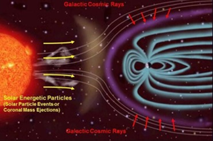
The sun is full of radiation, while our mother Earth's magnetic field shields us from most of the harm. On top of that, package material can be a serious contributor as well. As to exactly how physics interacts between the radiation and IC, I will leave that to the Physicists and Radiation Engineer to worry about. As a designer or engineer, you only need to know it's there and it's real. Then we'll need to figure out how to deal with it.
So hopefully, by now, I have convinced you that the effects are real and we need to take care of them for some of us. And we'll dive into the topic of FIT in the next part of this series.
Failure in Time – FIT
1 FIT = 1 failure in a billion hours. In other words, it takes around 114,155 years for an error to occur. Quality engineers will often mention MTTF (Mean Time To Failure) and MTBF (Mean Time Between Failure). Although one error in 114,155 years sounds abysmal, a generally assumed unmitigated processor with a FIT of 50,000 would mean a fault every 2.28 years. But this is one single processor. A system will likely have memories and many other ICs. It's a common consensus to use 1,000 FIT/M gates for unmitigated 90nm ASIC. And if you expect just to build 10,000 systems, the number adds up fast, and that accumulated number should be enough to send a chill down any quality engineer's spine.
Real Numbers to put things into Correct Perspective
AMD-Xilinx is the poster child in the SEU field when doing their due diligence and openly publishing their results. We're interested in the Device Reliability Report UG 116, updated every six months.
First, take a look at the figure below. Some FIT is already provided.
As engineers, it's our job to drive down the FIT during normal life or the region not covered by the bold red letters in the diagram.
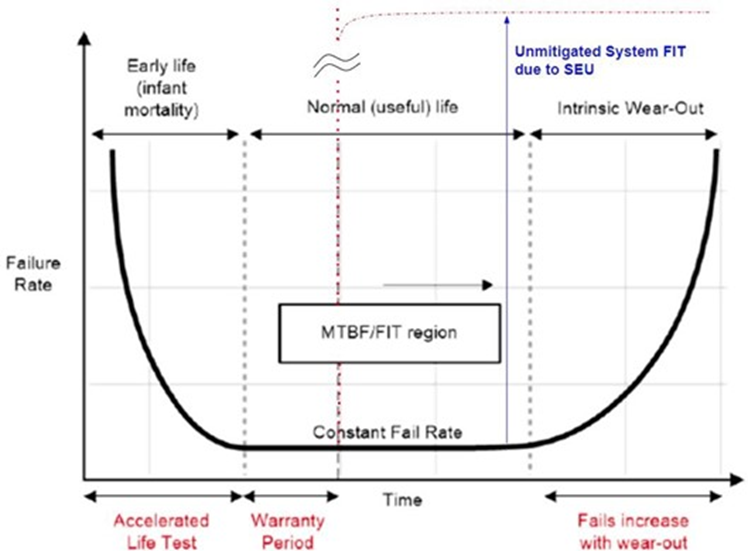
Table 19 should specify the various SEU-related FIT numbers for CRAM (configuration ram). For those unfamiliar with AMD FPGA, FPGA is an SRAM-based reconfigurable gate array device. Therefore, the user design must first be loaded into the configuration memory for the device to function as expected.
Look at the first three rows, all with tech nodes of 90nm but spanning 4 product families. As you can see, the LANSCE Neutron cross-section per bit is different. Moreover, the last two columns vary up to 2.6x between Virtex-4 and Spartan-3E/3A.
The lesson for this is that don't assume your 90nm will have the same superb number as AMD. They put in much work to reverse the technology trend to drive down the FIT. Otherwise, with each shrinking technology, one would expect it takes less energy to upset a cell while knocking out multiple cells.
It's also important to note that they're the only major house player I know who provides real-world data. If you merely follow the JESD89 conversion, you'll see there will still be quite a gap between the derived number and the real-world number.

The main takeaway here is that it's inevitable that IC will fall to SEU eventually, and the more advanced the node is, the worse the problem is unless you do something.
SEU Family Tree
It can be simply broken down into two categories:
- Hard/destructive
- Non-destructive
Hard errors are rare but catastrophic, while software is more common.
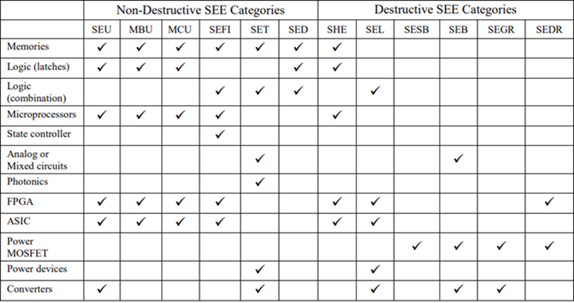
Before we move on, note that this table should be used as a baseline reference. For example, FPGAs are also vulnerable to SET, and it's just that the probability of an SEU is so much higher than SET that we should focus on SEU.
In addition, some of the errors will also be vendor or even device-specific. Do a quick search on FPGA and SEL, and you'll see that not all vendors and parts are vulnerable to SEL.
Non-Destructive SEE
SEU (Single Event Upset): General error that results in a functional error
MBU (Multiple bits Upset): Any single strike that knocks out bits
MCU (Multiple Cells Upset): MBU, but not limited to bits
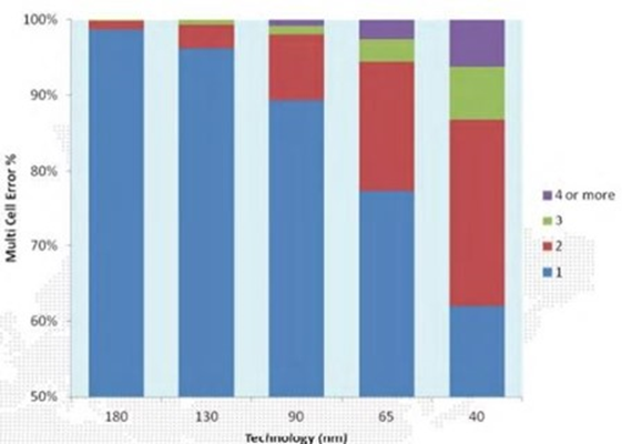
Most ECC deployment is based on SECDEC, Single Error Correct Double Error Detect. Therefore, aliasing can occur if an upset spanned more than three errors. Refer to the following generalized diagram; you're safe at 180nm, but at 65nm, ~20% of errors resulted in MBU.
At 40nm, you're now close to 40%, SECDEC is effectively useless. It's also true that the result can vary significantly pending foundry, cell layout, etc., but if you're unaware of this issue, don't expect the device vendors to tell you this voluntarily.
SEFI (Single Event Functional Interrupt)
Anything that knocks out the device function can be put into this bucket. For example, if an update knocks out your PCI bridge such that the device drops the packet and is no longer responsive to subsequent requests, it's a SEFI.
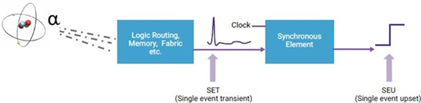
SET (Single Event Transient)
A picture is worth a thousand words. Try to imagine this glitch on the reset or clock line, but at the same time, a glitch on the data input without a clock likely isn't going to result in any error.
SED (Single Event Disturb)
Effectively just a dumpster for anything not covered by the other family members.
Destructive Errors
Most of these errors are self-explanatory by name. The common symptom is a damaged device which typically manifests itself with an additional current draw that can't be recovered even after a power cycle.
- SHE (Single Event Hard Error)
- SEL (Single Event Latch-up)
- SESB (Single Event Snap-Back)
- SEB (Single Event Burn-out)
- SEGR (Single Event Gate Rupture)
- SEDR (Single Event Dielectric Rupture)
Not All Errors Are Created Equal
After reviewing the SEU family tree, you should quickly see that not all errors are equal. Some errors significantly impact the system, while others may simply flush out with the system, even experiencing a
blip. SEUPI, Single Event Upset Probability Impact factor, is typically used to further derate the probability of an event that may result in actual errors observed.
Choices
As an engineer, many techniques are at our disposal to drive down FIT. Do note that some of the techniques discussed only apply to IC design, some for system or module designers, while all can deploy some. You'll also notice that many techniques can target the same failure. The choice is yours. It comes down to area, resource, speed, power, and all these constraining factors you get to deal with before you choose the option that best suits you.
For example, if you're an IC Designer and need to protect memory's integrity, you're limited to methods such as ECC, parity, scrubbing, interleave, cell type, etc. But as a system or module developer, you must deploy redundancy and software mitigation schemes such as SWIFT or simply log and optionally reset the module.
Mitigation Techniques
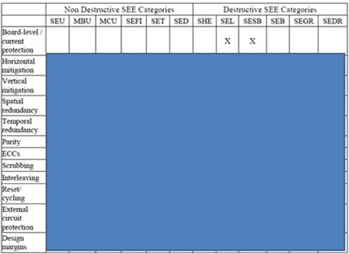
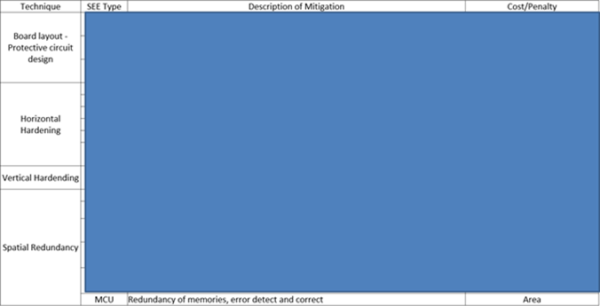
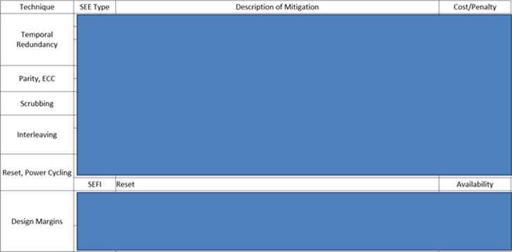
Now you see numerous techniques that we have at our disposal. For full tables, please follow up with me. But to demonstrate how even a simple technique does require plenty of expertise, we'll dive into one technique.
TMR - Triple Module Redundancy
Three times power consumption, area, resources, and complexity always equate to a thousand times happiness. IEC61508 provided some different variations of redundancy as well.
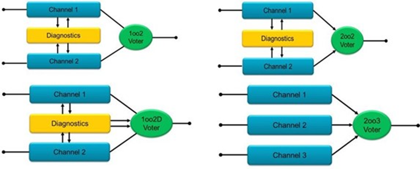
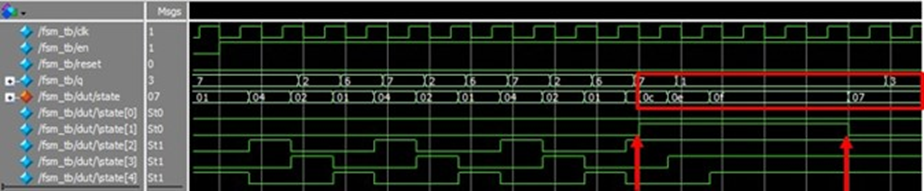
Now let's assume one of your 2oo3 voter channels is out due to SEU, but the error stays in the system because it's part of the one-hot finite state machine (FSM). The system now becomes up to twice as vulnerable to subsequent failure.
Let's look at another widely touted LTMR (Local TMR) scheme that protects flip-flops below.
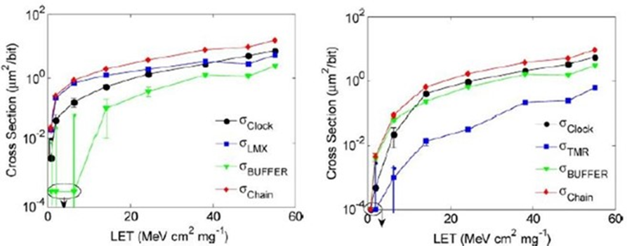
This is a shift register design that protects only flip-flops. The essence of the comparison is that the red line (Chain) is effectively the same, although the blue line (TMR flip flop) lowered significantly. In an FPGA, the configuration bits required to set the flip flop's content may pale compared to the number of configuration bits required to set routing. Therefore, performing redundancy without sufficient knowledge may be worse than not doing anything at all.
Mitigation Schemes Deployed by IC and System Providers
After all that talk, let's review the major IC players' actions. It's important to know that each IC households this deck of cards very close to their chest, and many published data may be outdated, but it still provides the idea that this SEU issue is not to be simply overlooked.
First, s/390 G5 provided by IBM had added 20~30% logic to protect its execution units and main process. Fujitsu claimed to have 80% of its 20,000 latches in Sparc64 covered, parity added to ALU, and checks done on multipliers and dividers.
Xilinx went even a step further with its Zynq family. It has completely separated PL (programmable logic) and PS (process) power, so you now have redundancy. This is in addition to providing two ARM's real-time processors so you can deploy schemes like lockstep and other software and design flow techniques that one can further deploy to drive down FIT. A lot of background work has been done so ASIL-C can be achieved on one part.
And if you google Huawei and SEU, NTT's 10G-OPON ONU+SEU, or Broadcom's WP SE-BSD-WP100, you'll see that system folks other than automotive folks have long been dealing with SEU. Cisco even had a radiation test team that listed SEU as a standard debugging step.
Verify as Soon as Possible
The design must inevitably be verified. A mitigated design only cranks up the pain meter. For anyone who codes in RTL, you can't escape writing test benches. And no, you don't get to check that done box just by implementing system verilog's random function.
And are we done after the simulation? Life can't be that easy, can it?
The general rule of thumb is still applicable. The earlier you catch a bug, the less hair you'll pull out.
Simulation
We know we can't cover all cases; therefore, getting bang for the buck is essential. Hit the clock line or reset line if they're also triplicated. Hit logic with high value so you can quickly validate how robust the code is. The list goes on, but you get the idea.
Fault Injection
FPGA emulation or FPGA designs provide designers with a quick and easy way to inject errors into the design on a bit-per-bit basis. And if you know your configuration well enough, you may be able to back-trace the failing bit to your design.
Accelerated Radiation Testing
This is the closest method you get other than real-world data collection. And if you're doing this for ISO26262 and following JESD89, you still have to think about all the nitty-gritty details if you've never done it before.
Let me just toss out a few things for you.
- What beam will you use? Alpha, proton, neutron, x-ray, focused laser beam?
- Will this be a dynamic or static test?
- What type of failure should you be looking for? Are you sure you can catch it and recognize it?
- What monitoring system would you deploy?
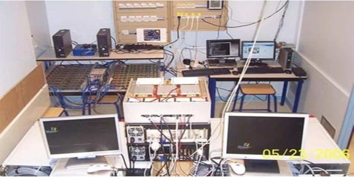
To provide you with a real-life example, let's look again at the AMD-Xilinx test setup for a "dynamic test".
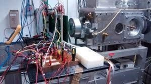
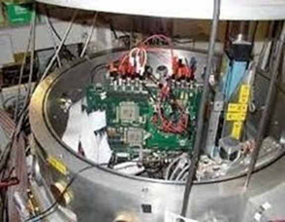
Two setups are provided here; you can tell one setup is in the open air while the other is in a vacuum.
The discussion of beam selection, test setup, and all the gotchas is a giant topic in and by itself. This is why some major commercial folks even have their dedicated radiation test team.
Frequently Asked Questions
1. What mitigation strategies or techniques can be employed to reduce the impact of SEU and power cycles on electronic systems?
The goal is first to reduce FIT rather than reset or power cycle the system. Reset or power cycle the system will bring down the system and result in user operation interruption and critical applications such as electric cars, which may result in life or death.
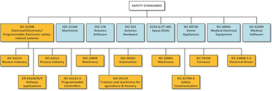
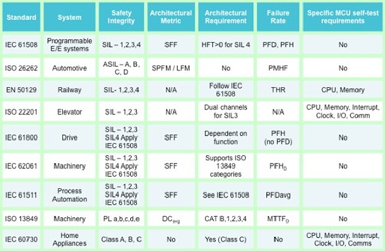
2. How do safety standards align with industry practices and experiences regarding SEU, and do they evolve to address emerging challenges in this area?
As you can tell, many applications already have. I'll append the pictures here for your reference. Most of the standards for the designers to refer to "experts" as the effect can differ dramatically pending IC technology node, vendor, foundry, etc. The knowledge in this field is lacking here in Asia. But of course, as the course has already mentioned, applications that can result in significant damage will also be a concern.
I've listed examples from Huawei and Cisco in the piece, I'm aware of systems in the financial world (accelerated trading platform), gaming machines, AI applications, etc, that, although not bound by the standards but are rather interested in this topic because they've already been burned.
3. How do high-reliability applications account for the potential occurrence of SEU in their system design and architecture?
Through design mitigation, engineers must first know the FIT (failure in time) rate to deploy the correct mitigation.
4. Are there any advancements or innovations in package materials that aim to improve SEU resistance?
As far as I'm aware, no. This is why the burden is now on the designer to deal with it.
Comments
No comments yet. Be the first to comment!